I was looking through DevonThink's Metalworking/New Projects list of 260 projects for something interesting and simple to tackle. I saw this train whistle project and decided it fit the bill. It is essentially 4 copper tubes held in a wooden mouthpiece. Two feet of 1/2" of copper pipe was needed, but Menards' smallest lengths were 5 feet. There were two grades with the same 0.625" O.D. but slightly different I.D.'s. I selected the thinner walled and cheaper grade. I doubt I have the lung power to explode this pipe!
This project came from the web.
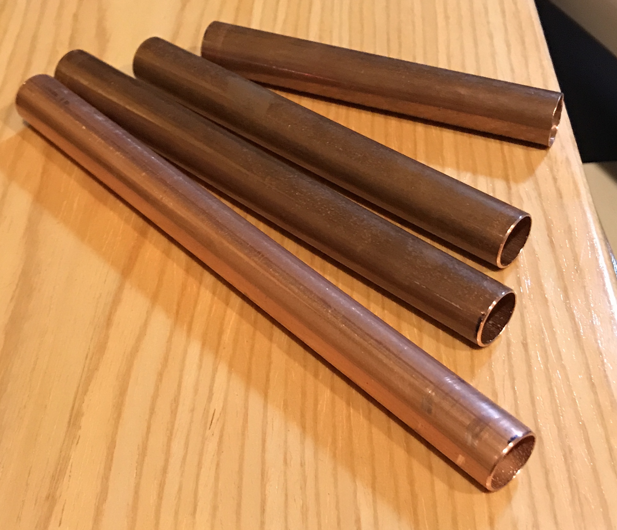
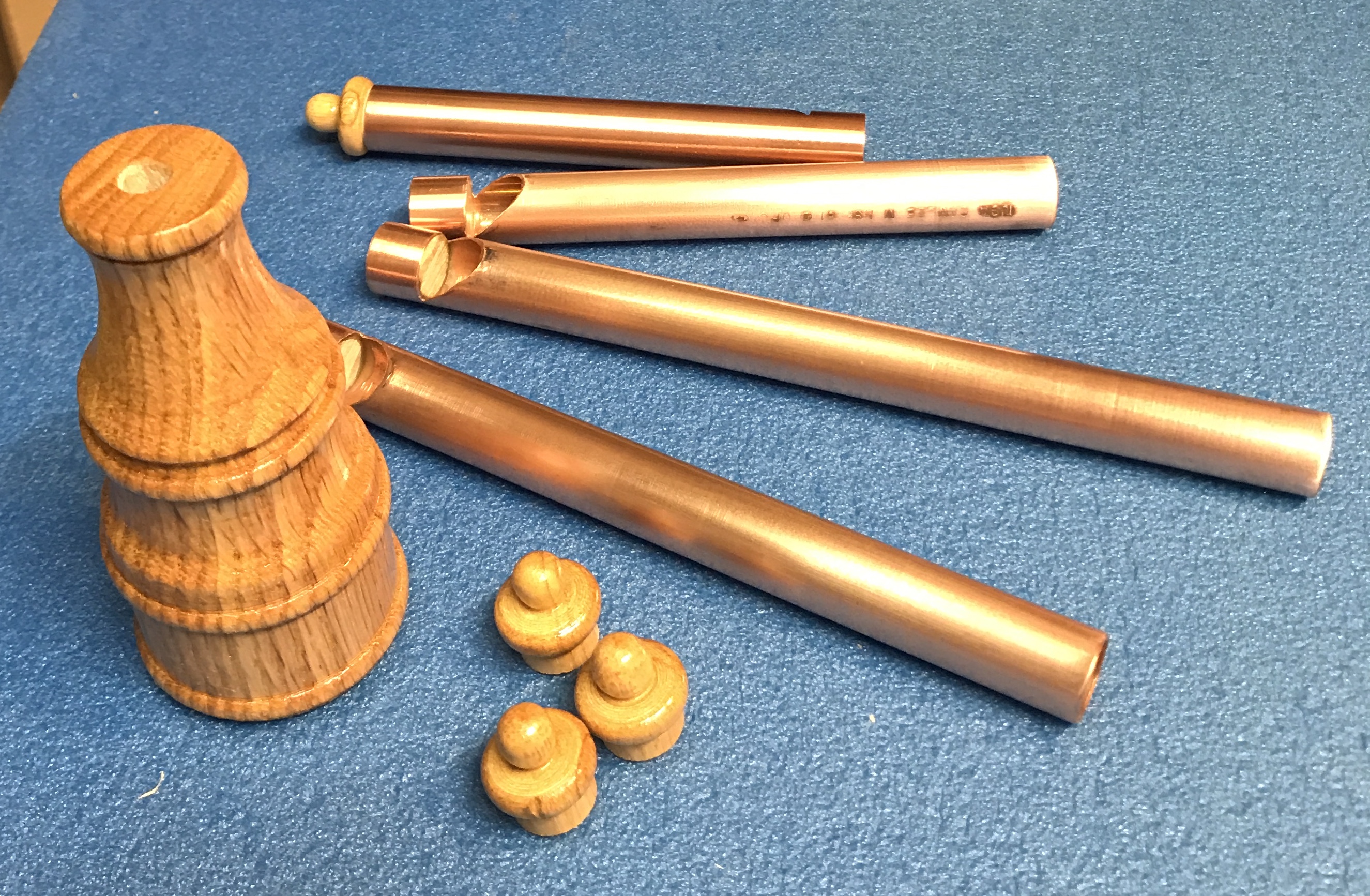
The copper pipe is first cut into four lengths: 4 1/2", 5 1/2", 6 1/2", and 7 1/2". A pipe cutter was used to do this. (After spending 30 minutes searching for it! It is now hanging in the garage, where I first looked for it.) The ends were then filed inside and out to get rid of any burrs while the pipe was spinning slowly in the lathe. (See below on internal burrs.)
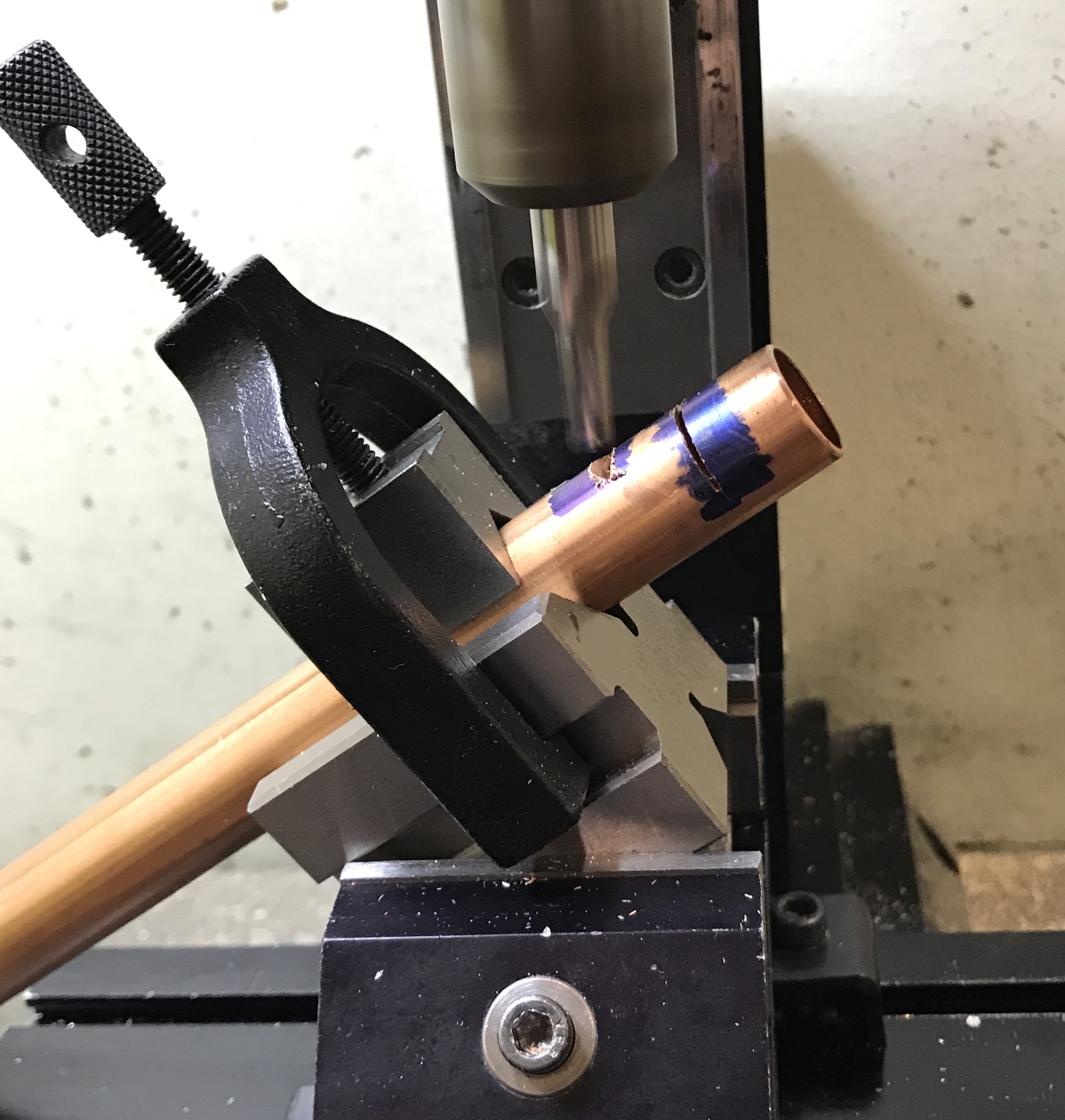
The next step is cutting the angled slot in the side of each pipe. The first cut starts at 1/2" from one end of the pipe. This cut should extend 180° around the pipe. The second cut is then started at 1" from the same end and angled to meet the two sides of the first cut. The second is cut 0.3125" deep and 1/2" long, so the angle is 32° (tan-1 (0.3125 / 1/2)). I think the best approach is to use a hacksaw to cut the arc at 1/2". Then follow with the end mill to remove most of the material. This all worked as planned. The picture below shows the setup for milling the angled cut.
A three-corner file was used to finish the corner. The same file as well as a small half-round file were used to deburr the hole. Finally the pipes were sanded on the lathe with 400 grit paper.
Found some interesting (but unwittingly useless) hardwood on the scrap shelf to use for the mouthpiece. A 7/8" X 4" X 5" block was cut in half. The two halves were glued face to face giving a 1 3/4" X 2" X 5" block. Nine holes need to be drilled before shaping the block on the lathe. A lengthwise 1/4" through hole and four 5/8" holes 3/4" deep on one end to hold the pipes. Holes to connect the four holes to the through hole also need to be drilled. The wooden block was center punched and set up in a vise on the large drill press in the garage with a stop. The vise was adjusted so a center punched hole was centered under the drill bit. The hole was drilled half-way through, the block flipped and repositioned and the other half was drilled. Surprisingly, the holes met on center. There was significant smoking during the drilling process, but the wood showed no signs of burning.
The next set of holes was laid out on one end of the block. The block was again set up in the large drill press in the vise. A 5/8" Forstner drill was centered over one hole. Drilling commenced only to stop about 3/8" deep. The smoking was too intense. A slower speed might help, but the drill press goes no slower. There was significant char in the hole and on the drill bit. The bit was not damaged, just dirty. I do not know the type of wood, but maybe due to sap it has a low charring temperature. Time to start over. I think the biggest problem is the speed. The recommended top speed for the 5/8" bit is 500 rpm in hardwood. I may need to use the lathe with the work offset in a four-jaw chuck to drill the four holes, but not in this wood.
The Forstner bit and the spade bit used in the aborted drilling were both soaked in Uncle Bob's $3.99 - 2009 "Gum and Pitch Remover" from Sears. A little work with a toothbrush delivered a refurbished Forstner bit.
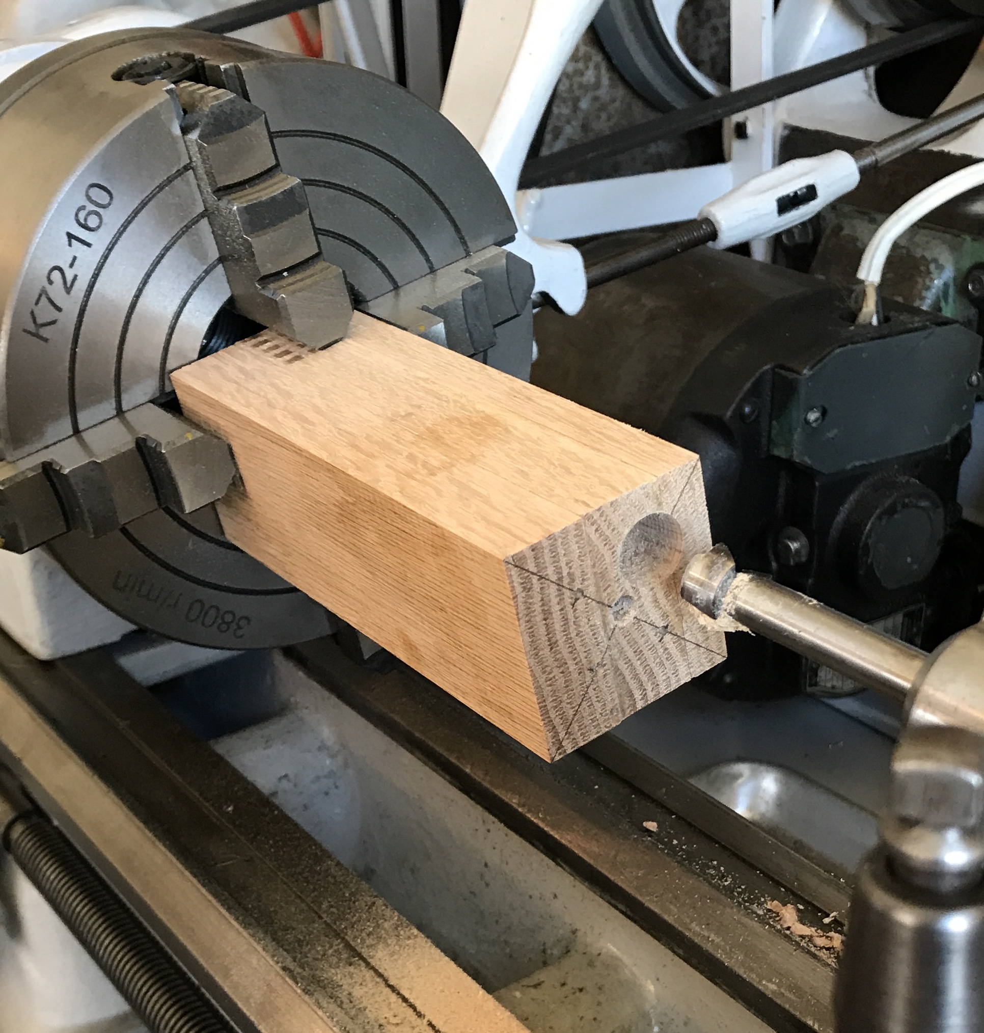
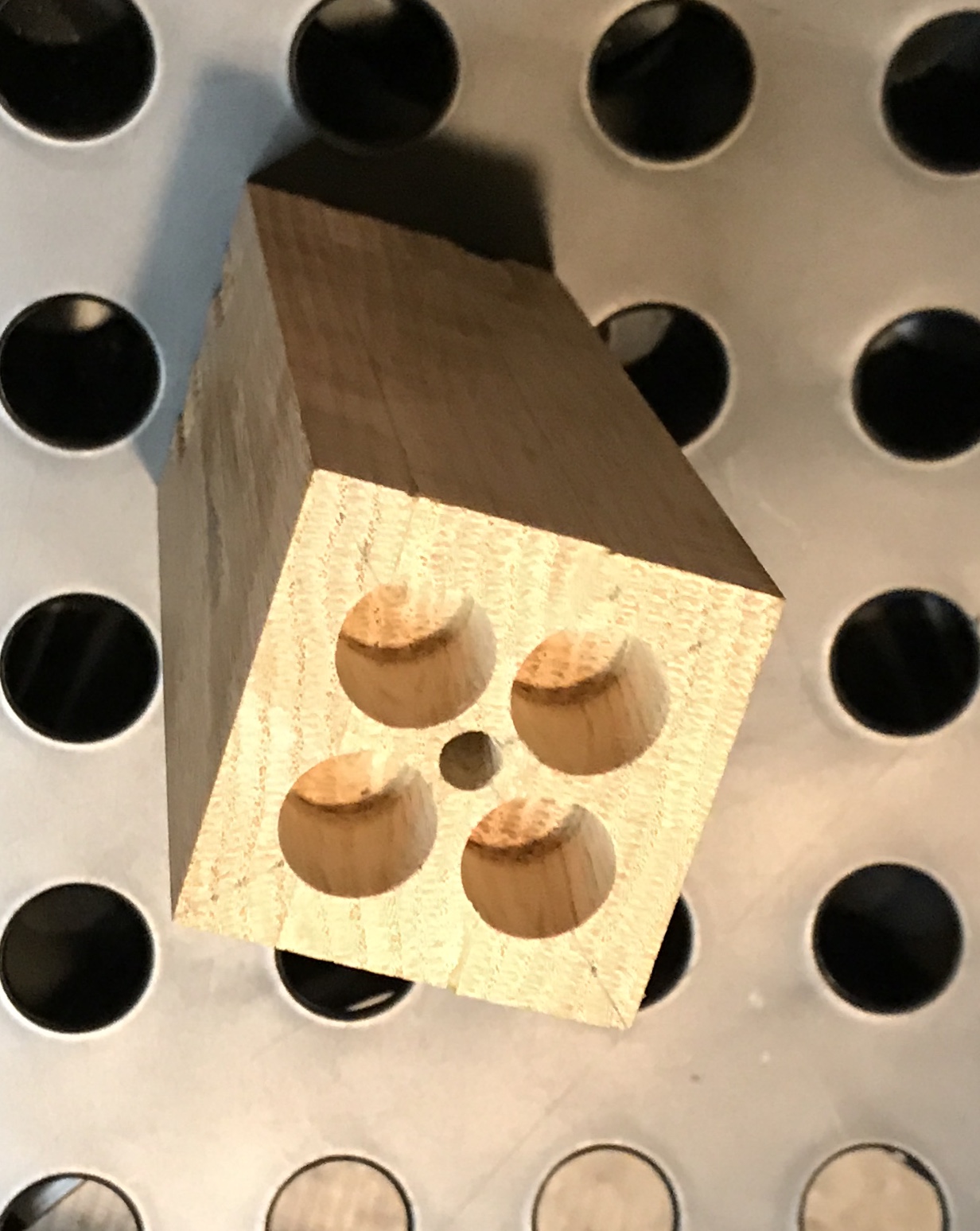
From a scrap of 3/4" oak three 2" X 6" lengths were cut. These three boards were glued face-to-face and left to dry overnight. Glue was removed with a chisel. The block was then cut to 2" X 2" on the table saw and sanded smooth on the belt sander. The center was measured and marked. Two lines were drawn corner to corner and 1/2" was measured out from center along each of these lines. Punch marks were made on each of these four spots. The block was clamped in the four jaw chuck on the Southbend lathe. It was simply centered with the drill in the tailstock chuck. A 1/4" hole was drilled about 3" deep and then the drill was switched for a 6" long spade bit. This was able to drill almost through. The block was then offset about 1/2" in two directions to align one of the punch marks with the 5/8" Forstner bit. A hole was drilled 3/4" deep at 1100-1200 rpm (as read from the inverter). Drilling was a piece of cake! The block was rotated 90°, recentered and the drilling repeated. After two more rotations the four hole were complete. The first picture below shows the lathe setup after drilling one hole. The second picture shows the completed block.
Finally, the block was held in the bench vise and connecting holes were drilled (1/4") from the bottom corner of the 5/8" holes to the center hole. After some clean-out the block was complete and ready to be shaped.
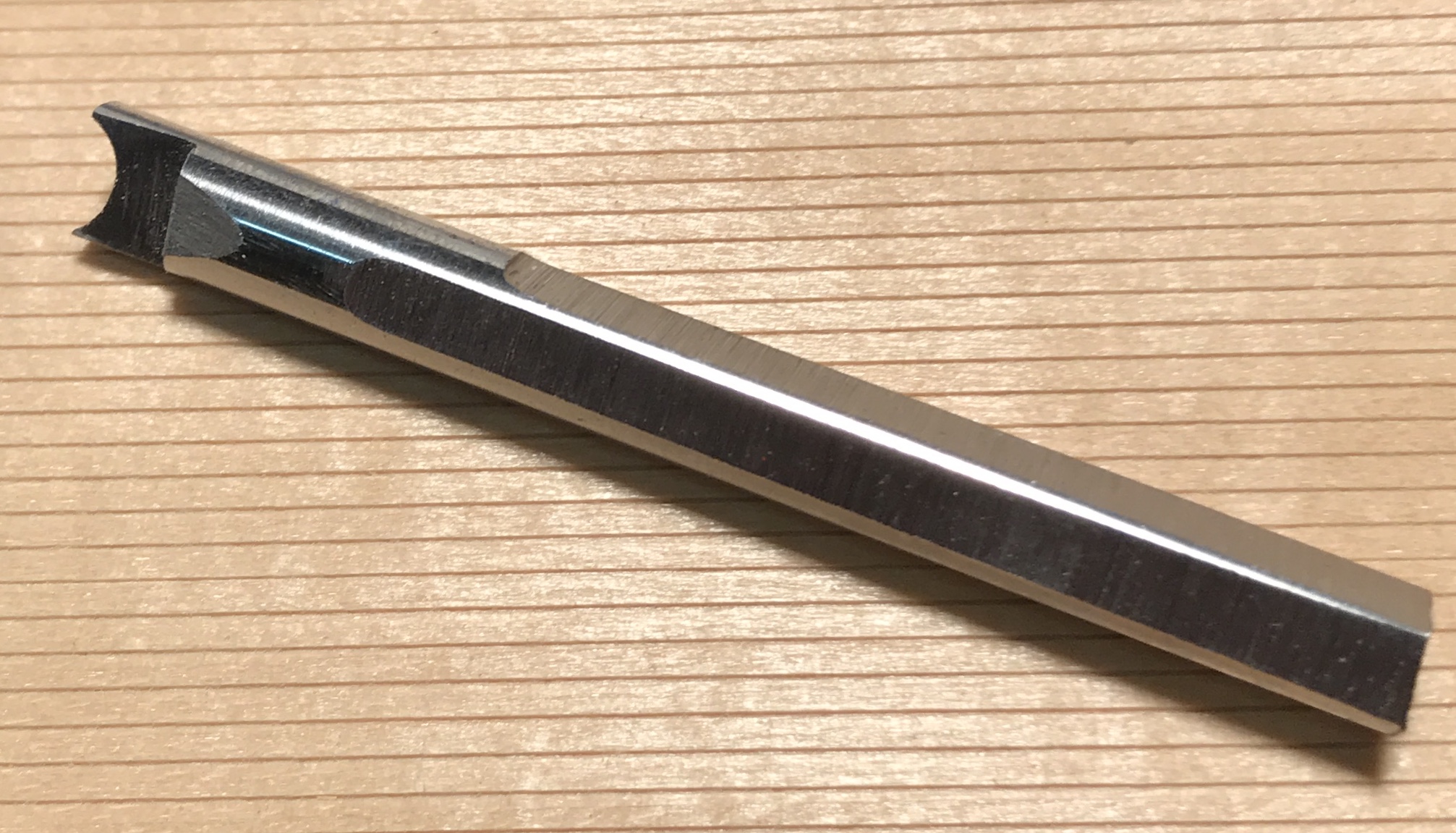
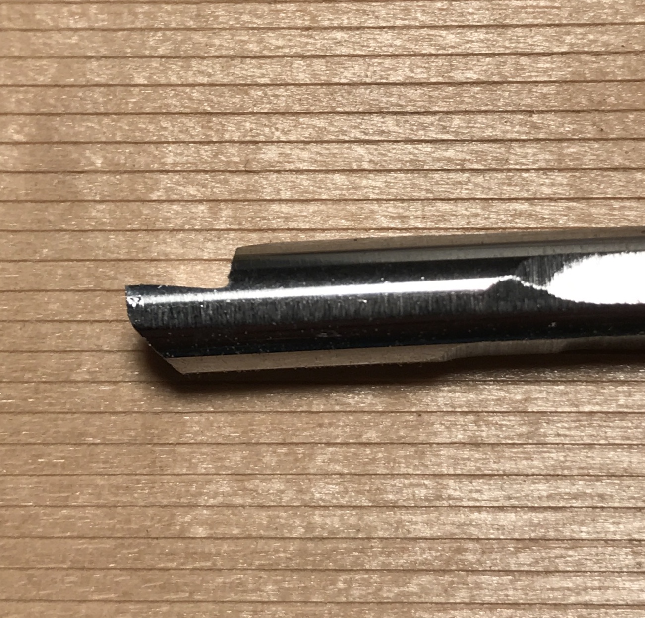
First, some thoughts on making a 1/4" radius tool for woodworking. This tool is needed for making decorative details on the end caps and the whistle body as seen in the first photo. It is made from 1/4" drill rod. One end of the rod needs to be squared up for holding in the lathe. The other end needs to be ground/filed from the top to give a flat with a small back rake. The flat end can be filed to provide clearance and then filed further with a round file to provide the 1/4" half round groove also with a little clearance. When complete the business end of the tool should be hardened.
Making the U-tool worked out pretty much as planned. The four flats were done with the belt sander. For each successive face after the first, the newly flattened face was held against a block of wood while the next face was ground. The blank was then held in the vise by the flats and the front end was filed flat and with some relief. The top had some material removed on the belt sander and then a file was used to flatten and add some rake. The front and top were sanded up to 600 grit. The slowest part was filing the U-shaped groove. This took about ten minutes using only the first two inches of a round file. (Beyond the first two inches the file was too big.) A little work was then needed to make sure the two sides of the U were symmetrical. The first picture below shows the tool as ground and the second picture shows the relief and rake. To finish the tool, it was heated to cherry red for about one minute and then quenched in oil.
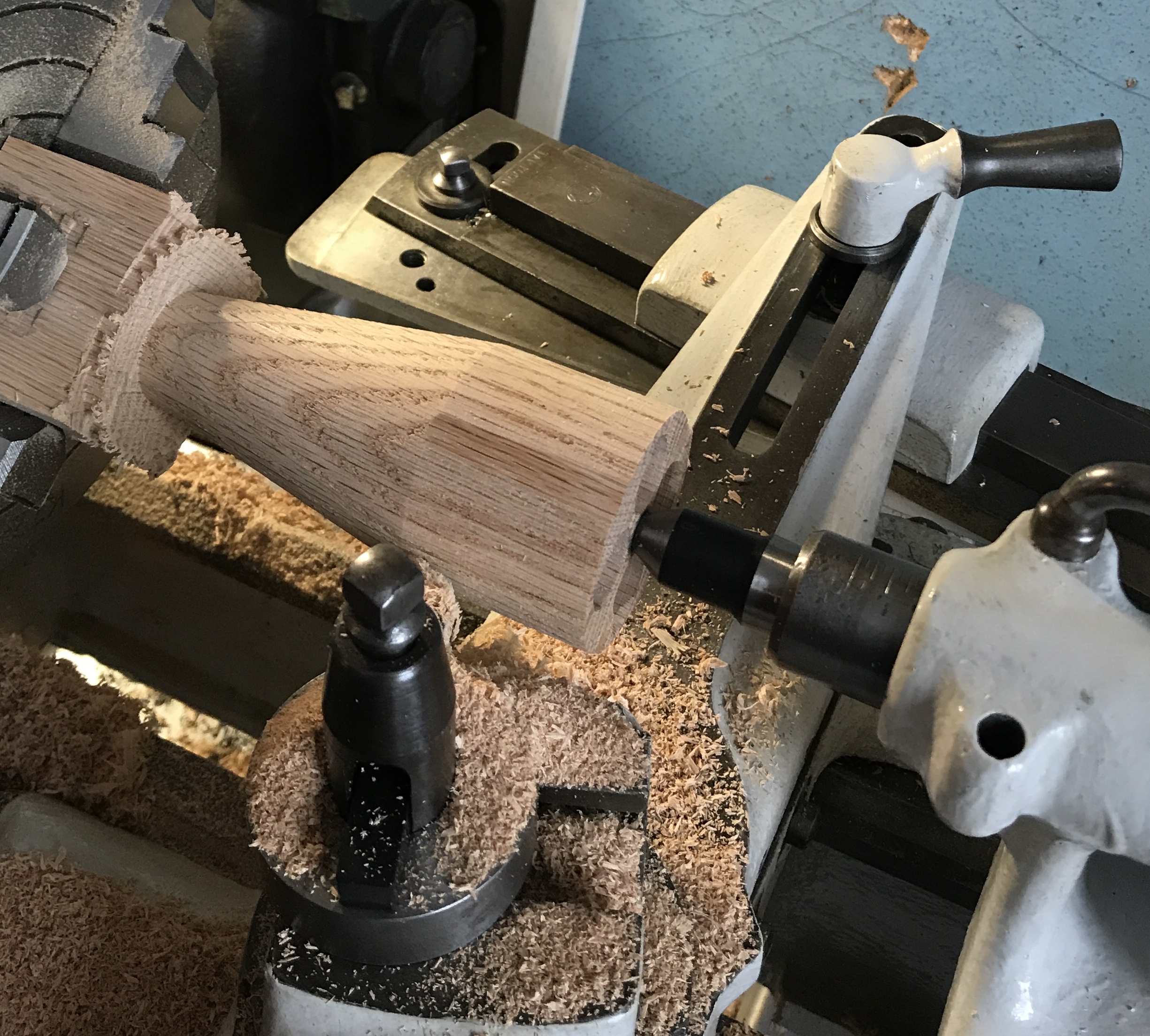
The taper attachment on the Southbend was used to cut the taper. The narrow end of the taper is close to the headstock, so I consider that a negative taper. The block was marked with a pencil at both the narrow and wide ends of the taper. Two screws on the taper attachment needed to be moved to get to "negative" angles. [One is seen top center in the picture below.] The angle was set to -10°. The cutting tool was moved to the narrow end against the wood. The tool was moved to the right with the taper attachment tightened to the cross slide. The cross slide clamping screw [top right in the photo] was loosened, the tool advanced 0.030", and the clamping screw was tightened. With the lathe running at 1100 rpm the tool was advanced and the taper was cut to the line. The taper was lengthened about 1/8" per pass. This sequence; loosen clamping screw, advance cutter 0.03", and tighten clamping screw, was repeated between each pass. The cross slide did not move freely with the advance of the lead screw, so both dials needed to be moved simultaneously. [The cross slide handle just needed minimal pressure to track with the taper.]About two-thirds of the way through the cutting process it became clear that 10° on the taper attachment was insufficient. The markings on the attachment must refer to included angle. So at this point the attachment was adjusted to -20° included angle. This is the limit for the taper attachment. The photo below shows the completed taper. The narrow end is 1.00" in diameter.
This was the limit of my endurance for the day. The garage was 40°! I had to wear a vest and gloves.
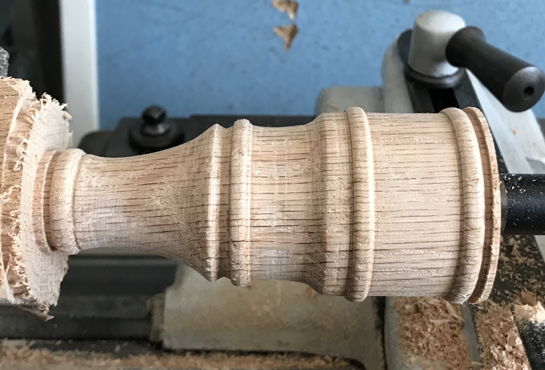
Shaping the mouthpiece was done this morning at a toasty 35°! First the locations of the half-round protrusions were marked. A cutoff tool was used to make grooves at these locations about 1/16" deep. A half-round rasp was used for most of the shaping, both the flat and round sides. A full round rasp was also used in a couple of locations where more curvature was required. I generally followed the shape of the whistle mouthpiece shown in the web site, but mine is certainly not a replica. After shaping to some degree of acceptability, the tool bit made above was used to round over the four protrusions. A strip of sandpaper (150 grit?) gave an acceptable finish. The picture below shows the completed shaping. Just facing and parting off remain.
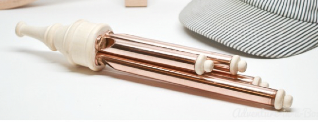
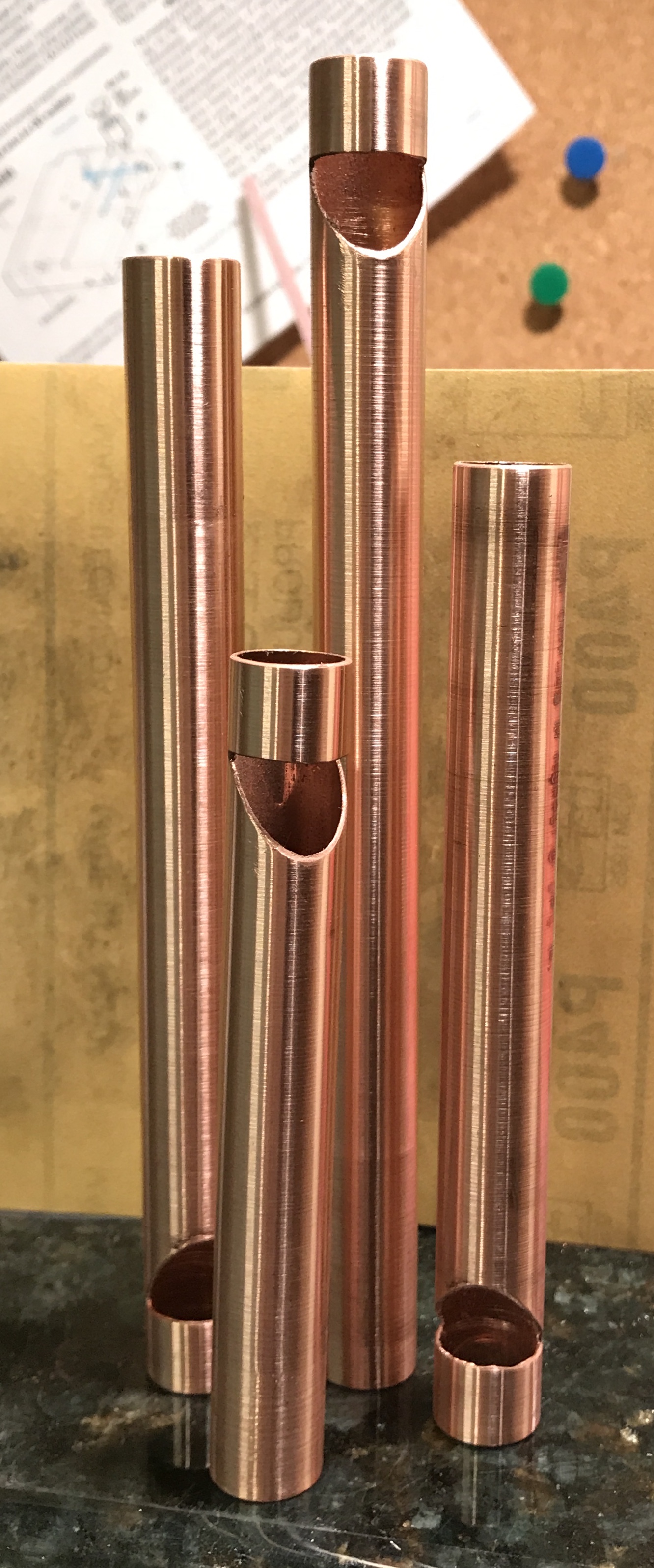
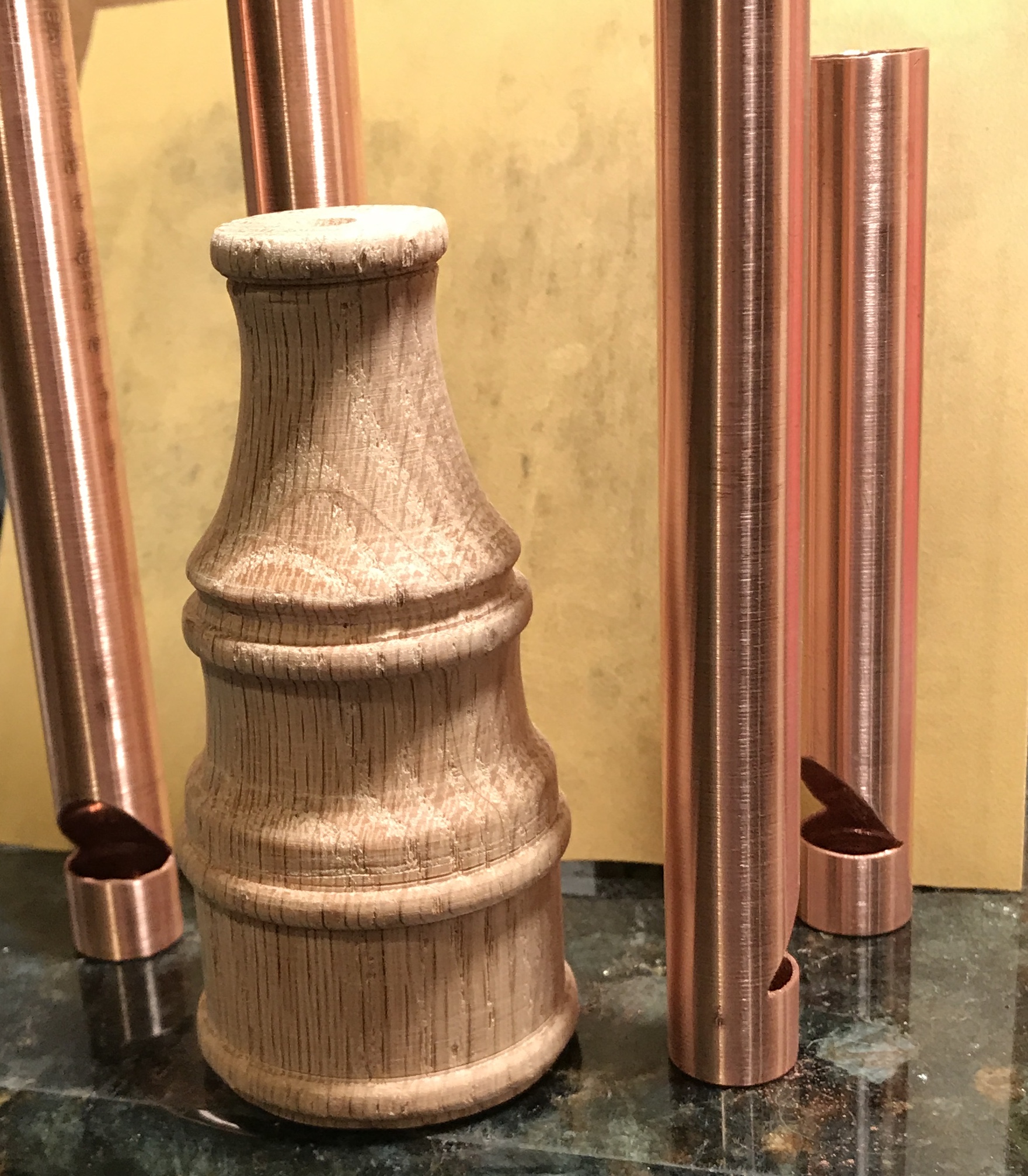
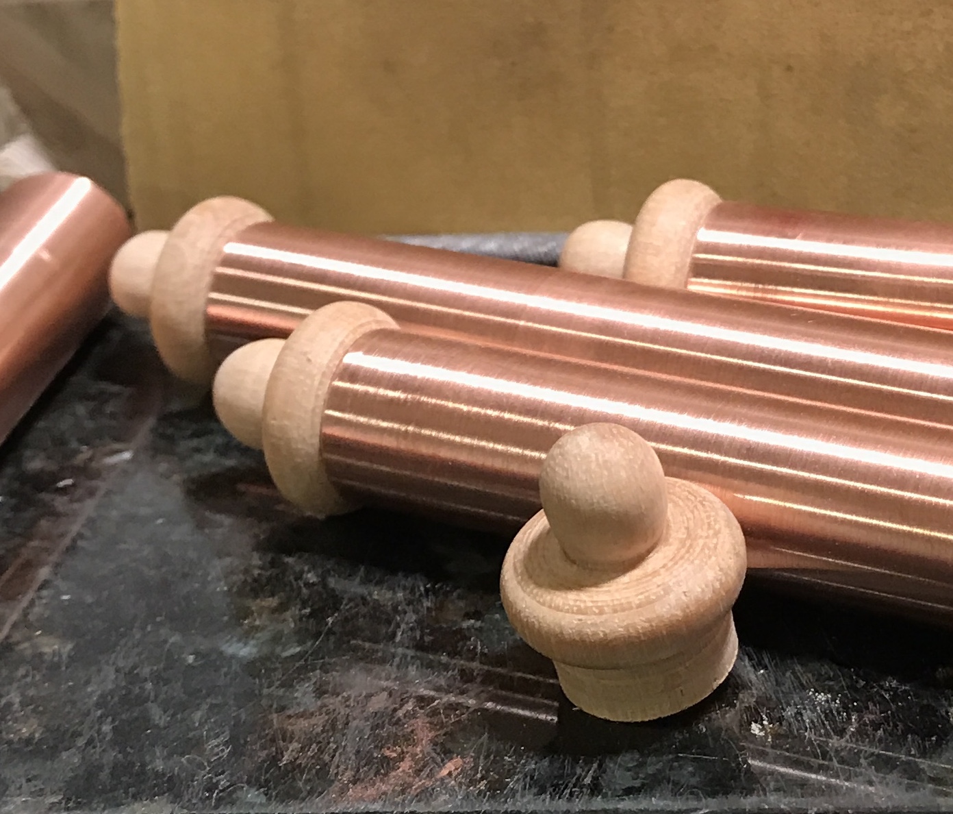
After a bit more sanding the tailstock center was removed and the large end faced. This was probably not a great idea. There was significant chipout in the four large holes. Either they should have been plugged or the end should have been sanded. The mouthpiece was then parted off with a cutoff blade. The end was quite smooth. A 1/4" dowel was loose in the center hole, so 1/4" of 5/16" dowel was sanded lightly, cut off, and glued into the center hole on the wide end. This plug was then sanded, but left a bit proud. The mouthpiece is shown in the following photo in a tube forest.
In general oak should not be machined in the lathe. The grain is not sufficiently close-grained resulting in significant roughness over the surface. Many little nicks can be seen in the photo below.
Plugs were made for the notched ends of the tubes. The ID of the tubes is 0.57". When measuring I realized that the ends of the tubes have an internal "lip". This is probably a side effect of the tubing cutter. This lip was removed with the handheld countersink. A 2 1/2" length of 3/4" dowel was reduced to 0.57". A flat was filed on top removing about 1/16". Slightly less than 1/2" lengths of this dowel were cut off with a back saw. These lengths were glued into the tubes: aligning one end of the plug with the bottom of the notch. Wood glue was used to make the bond. Meanwhile, the first coat of Tung oil was applied to the mouthpiece and left to dry for 24 hours.
Finally, the caps were made. A 1 3/4" length of 3/4" dowel was chucked in the lathe. The dowel was faced and 3/8" was reduced to 3/8" for the eventual ball end. The dowel was marked 1/4" beyond this and then about 1/2" of dowel beyond this mark was reduced to 0.57" to fit in the pipe. The rounding tool was used to profile the 1/4" protrusion between the two reduced sections. It had to be fed into the work very slowly to avoid popping the dowel out of the chuck. A combination of wood rasp, three-corner file and sandpaper was used to make the final profile. The cap was parted off to produce a 1/4" length of the 0.57" section to fit in the tube. After three repetitions of this process all four caps were completed as shown in the following photo.
A second coat of Tung oil was rubbed onto the mouthpiece and the caps were treated with their first coat. And on March 1 the last coat of Tung oil was put on the mouthpiece as well as a second coat on the caps. The smallest tube was selected for a buffing trial. It was held on the "to be glued end" and with needle nose pliers inserted into the top end. It was buffed with red compound on the brass buffing wheel. I couldn't really tell any difference in the finish as it was covered with black powder. It was buffed all over for about 5 minutes. A paper towel removed 90% of the black residue. This was followed by a soap and warm water wash. It was then dunked in acetone, while held with a bent paper clip. (No real difference relative to the unpolished tube was apparent!) The paper clip was affixed to a the top of a cardboard box and the tube was sprayed with clear Krylon. It looked ok after drying, but some "orange peel" can be seen. The last three tubes were not polished, but were sanded with 1000 grit paper, wiped clean, and dunked in acetone. They were also hung in the box and sprayed with a clear coat. Their color is slightly lighter than the "polished" tube, but the polished tube is shinier. Maybe the best approach would have been to sand to 1000 and then polish.
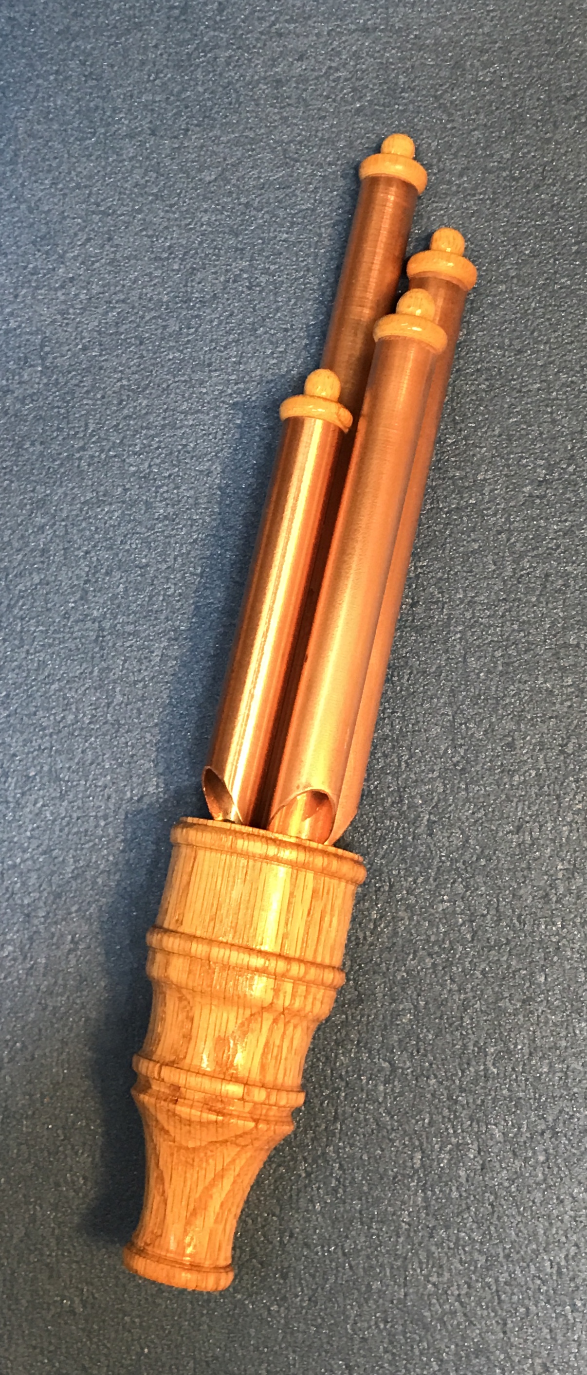
The caps were glued into the open ends of the tubes with wood glue. After letting these dry for an hour. the tubes were glued 1/2" deep into the mouthpiece producing the finished product. A cheesy sound clip is included below.